Pioneering Next-Generation Propulsion Systems
Advanced propulsion research grounded in modeling and simulation — high-fidelity compressible flow analysis, checked against closed-form theory and experimental correlation before it informs a design decision.
Core Focus Areas
Advanced Propulsion
Researching and modeling novel thermodynamic cycles, from nozzle and inlet aerodynamics through to unsteady, pressure-gain concepts.
Modeling & Simulation
Compressible and supersonic CFD, shock-capturing schemes and conjugate heat transfer — every model paired with a quantitative validation case.
Computational Tooling
Custom simulation software: parametric CAD-to-mesh-to-solve pipelines that make a design sweep a single reproducible command.
Modeling & Simulation
A simulation is only worth as much as the evidence behind it. Each case below is built from parametric CAD, meshed to an all-hexahedral grid and solved time-accurately with a density-based shock-capturing scheme — then measured against the analytical or experimental result it is supposed to reproduce. All of it runs on desktop hardware in minutes.
Converging–diverging nozzle starting transient, NPR 25. Mach number over numerical schlieren, 41,400 cells.
Case Study — Supersonic Nozzle
Shock Diamonds and Nozzle Performance
A planar converging–diverging nozzle exhausting to atmosphere, swept across four operating points from heavily overexpanded to strongly underexpanded. The shock-cell structure, plume spreading and exit conditions all follow directly from the pressure ratio.
- Exit Mach vs isentropic theorywithin 1.1%
- Mass flow scaling with chamber pressurewithin 0.003%
- Operating points solvedNPR 3 → 25
- Runtime per operating pointminutes, 6 cores
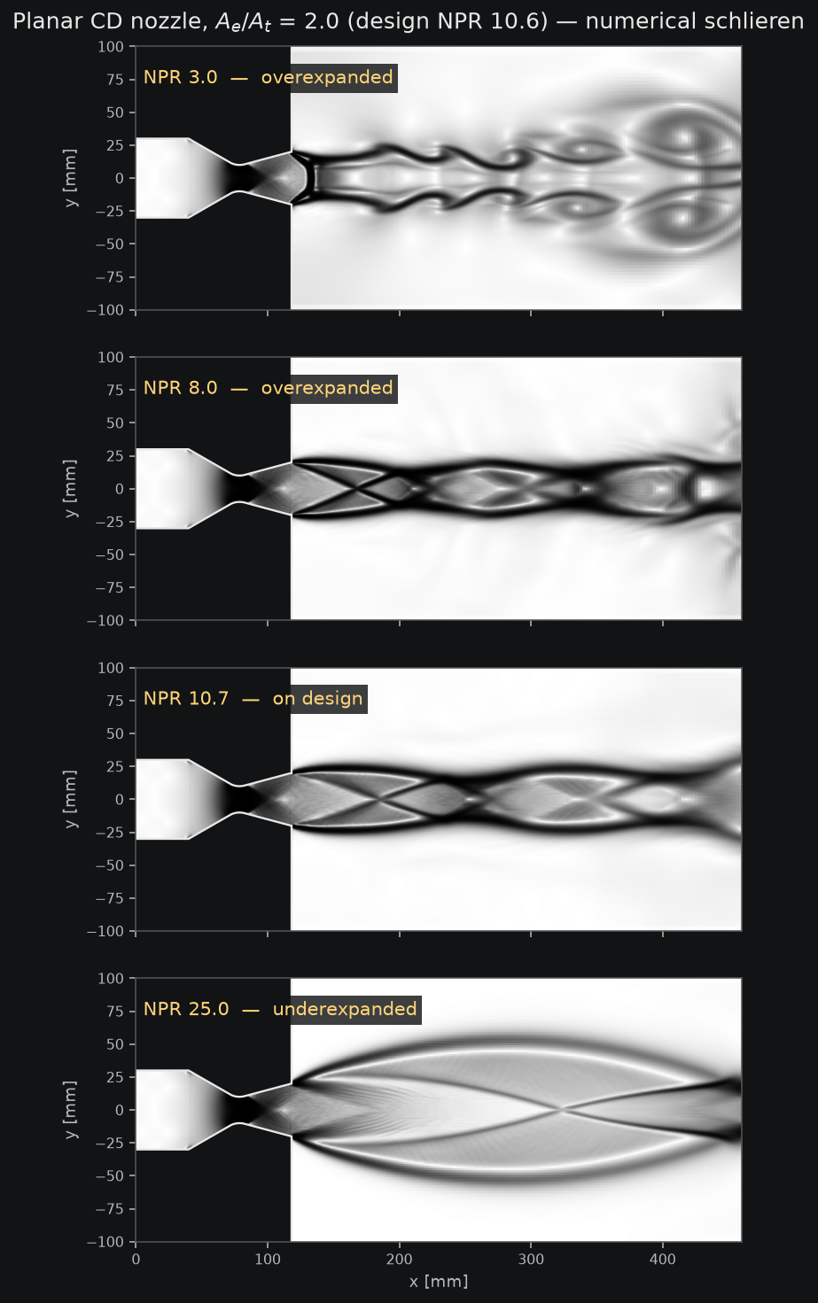
The same nozzle at four pressure ratios. The shock-cell pattern collapses as the design point is approached, then reverses.
Why It Matters
Off-Design Behaviour, Predicted
A nozzle is rarely operated at its design point. Resolving the overexpanded and underexpanded regimes shows where separation, plume spreading and thrust loss actually appear — the information needed to choose an area ratio, rather than to explain a test result afterwards.
Because the geometry is parametric, an area ratio or chamber pressure change is one command away from a fully re-meshed, re-solved and re-validated result.
Bow shock forming ahead of a cylindrical forebody at Mach 4, 11 km altitude. Mach number, 22,350 cells.
Case Study — Hypersonic Blunt Body
Bow Shocks and Stagnation Heating
The canonical re-entry problem: a detached bow shock ahead of a blunt forebody, solved from Mach 3 to Mach 6. Shock standoff distance, stagnation pressure and stagnation temperature are the quantities that size a thermal protection system — and all three have exact or experimental references to check against.
- Stagnation pressure vs Rayleigh Pitotwithin 0.6%
- Stagnation temperature vs isentropicwithin 0.4%
- Flight conditions solvedMach 3 → 6
- Grid convergenceverified, 2× refinement
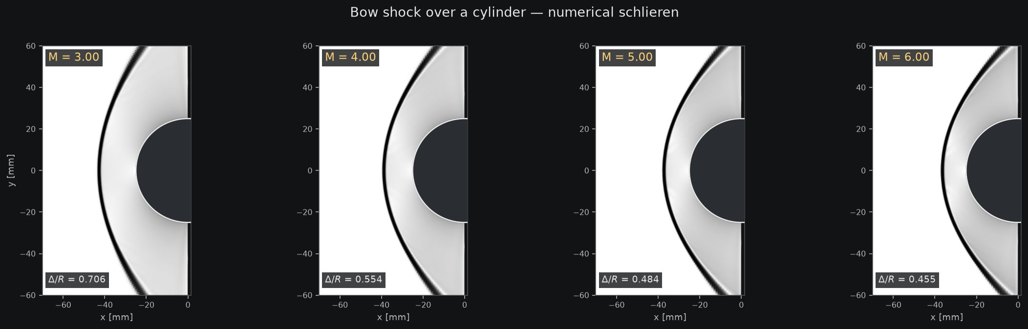
Bow shock at Mach 3, 4, 5 and 6. The shock moves closer to the body as Mach number rises, and the shock layer thins.
Why It Matters
One Model, Across the Envelope
A model that is only calibrated at one condition is a curve fit. Running the same setup unchanged across a four-point Mach sweep, and holding agreement at every point, is what separates a predictive model from a tuned one.
The same approach extends to inlets, forebodies and interference heating — wherever a shock system drives the loads.
Validation
Measured Against Experiment
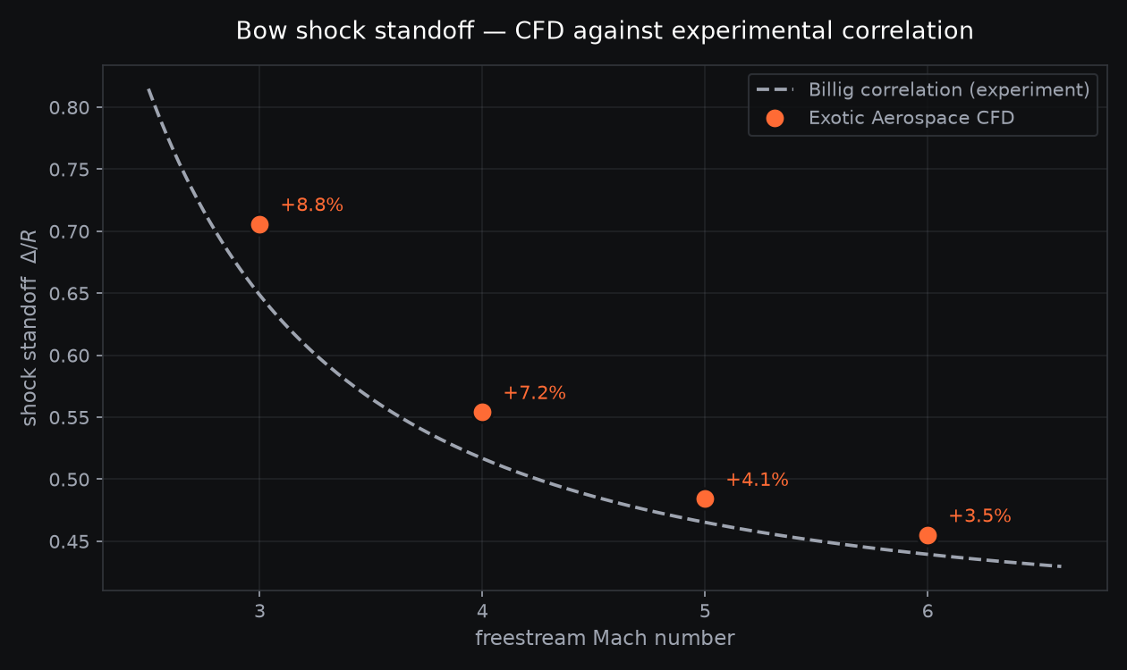
Four independent CFD runs against Billig's experimental shock standoff correlation. The offset narrows from 8.8% to 3.5% as Mach number rises — the expected signature of finite shock-capturing resolution, not a physics error, and confirmed by grid refinement.
Every case ships with its validation report, its mesh and the script that reproduces it. Nothing here is a picture without a number behind it.